
How to build an arcade machine
Inspired by a post from my friend Drew I’ve set myself a little project to build a modern arcade machine while we are temporarily staying with my wife’s parents and have access to my father-in-law’s workshop :). I first got into arcade games when I was around 10 years old. I still remember the first time I spent my hard earned pocket money inserting a coin into the Street Fighter II machine at my corner shop only to get decimated by the older teenager who challenged me. Over the years I’ve played on many pinball and table top arcade machines. At 14 I took my first job in the games arcade and this is where I mastered driving games such as Daytona and Ridge Racer. From then on I spent many hours in arcades like Timezone playing games such as Mortal Kombat II, Killer Instinct, Time Crisis I & II, NBA Jam, Initial D and more.
I’m going to update this post step-by-step as I go.
Step 1: Purchase materials
I’ve spent a few hours researching what I need to do and what I need to get. Assuming you have many parts and tools already, be prepared to spend £300 minimum getting what you need. Search the internet for cabinet plans but if you don’t have the tools or know-how you can buy flat pack cabinets or even an old cabinet off eBay to restore.
Cabinet
- MDF (18mm)
- Lengths of planed smooth whitewood (L)1800mm x 4
- Acrylic for the marquee (3mm), screen (2mm) and control panel (3mm)
- Black 3 Quarter Inch T Molding (40 feet)
- Aluminium Door Kickplate complete with fixing screws (650 x 150mm)
- 4 x Swivel Heavy Duty Rubber Wheels (50mm)
- Blackfriar Quick Drying MDF Acrylic Primer Undercoat
- Dulux Paints 2.5 Litre Ready Mixed Matt
- Black gloss spray paint suitable for plastic
- 2 Gang Power Extension Lead 2m BLACK
Control Panel
- IL Euro Joysticks & IL Concave Buttons & I-PAC2 Wiring Kit
- IL Convex PSL-CV Translucent Arcade Button
Display, Sound & Lighting
- AOC E2460SD2 24-Inch Widescreen LED Full HD Monitor
- Ultra Slim 3D LCD TV Monitor Wall Mount Bracket
- Mosfet Stereo Sound Amplifier Kit (Metal Speaker Covers)
- TENSEE 100cm USB Cable LED Strip Light (Cool White)
Graphics
- Spin Collective Space Invaders 115cm x 60cm
- Pacman Classic Wall Sticker Vinyl Decal 100×55
- Retro Console Controller Decal
- 2 x Atari logos
- Custom graphics for the marquee and control panel
PC
Software
Tools & equipment
- Ideally you have a workshop/garage with plenty of electric tools such as a router, table saw, jigsaw, drills and hole-saw drill bits, palm sander, clamps, screwdrivers, hammer, screws and bolts etc.
Step 2: Build the cabinet
As Drew mentions you can find cabinet designs here and control panel layouts here. I opted for a control panel layout similar to that of the X-Arcade Joystick.
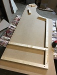
First you need to cut your MDF and drill the holes and slots. These are the dimensions I’m working with:
- Side panels: 1675mm x 635mm (the back edge is 1580mm) with 1 x 28mm hole on each side
- Back panel: 1568mm x 660mm with 6 x 70mm holes and 3 x slots for ventilation
- Kick panel: 1010mm x 660mm with 3 x 28mm holes for 1P, 2P and power
- Base: 525mm x 660mm with a 28mm hole cut out of the back edge for cabling
- PC shelf: 525mm x 660mm with a 28mm hole cut out of the back edge for cabling
- Control panel: 245mm x 660mm with 16 x 28mm button holes and 2 x 28mm joystick holes
- Monitor panel: 210mm x 660mm
- Top panel: 190mm x 660mm
- Speaker panel: 124mm x 660mm with 2 x 50mm speaker holes


Using a router cut t-mold grooves all the way around the side panels. Also cut a groove into the front of the control panel.


Next cut your supporting timber to the lengths shown below – 2 pieces of each except where specified. I used 34mm x 34mm which is excessive and caused a small problem when fitting the side buttons but it’s what I had available. Drew used 18mm x 18mm which will keep things a little lighter, simpler and cheaper. You can go all out with plastic fixing blocks if you like but the timber makes for a sturdier build. Use plastics fixing blocks in places where you might need to open the cabinet up to change things (e.g. control panel, rear access panel, PC shelf).
- Front (upper) 179mm
- Front (lower) 635mm – my images show me using the longer front timber as the upper piece but I later decided not to use a PC tower case and instead install an open motherboard mounted to the wood. To make this work I had to raise the PC shelf. Therefore I recommend using the shorter piece up top and the longer piece down lower.
- Base & PC shelf (front) 590mm
- Base & PC shelf (side) 525mm x 4
- Monitor 210mm
- Control panel 179mm
- Top 150mm
- Speaker 105mm
- Rear – use plastic fixing blocks
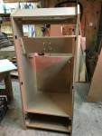
Glue the timber to the side panels except for the base (front) timber which you should glue and screw to the front panel. Remember to leave 18mm gap for the back panel as well as a gap for the PC shelf. I’m going to use plastic fixing blocks for the back panel so I can remove it easily when I need to access the PC and control panel for upgrades or repairs.
Once the glue has dried, drill pilot holes into the pieces of timber and drill countersunk grooves. Then fix the timber with 40mm countersunk screws. Drill pilot holes into the speaker panel for later when it comes to fit the speakers, and drill pilot holes into the base and fit the wheels. I ended up fitting my wheels with a too low profile (uncovered when fitting the t-molding!) and had to fit some wood spacers, so ensure you leave a little extra clearance.

I fitted the VESA mount bracket to the monitor panel now because I figured it would be easier doing it before the cabinet is assembled. Just follow the instructions that came with your mount.

Monitor panel with mount
Now it’s time to put it all together with wood glue and screws, however do not attach the control panel just yet – do this later on – just loosely sit it in place for now. Saw, chisel and sand any bits and pieces that don’t quite fit as they should. I also used some wood filler to cover a couple of external screws and scratches. The good thing about working with wood is that errors can be ironed out easily enough – most of the time!
Wearing a mask, give all the MDF a light sanding to remove any inconsistencies in preparation for painting. You can also order your acrylic at this point as you will have your exact dimensions for the marquee and display area which are likely to differ from your plans by a few millimeters.


Step 3: Paint the cabinet
Lay down 2 coats of MDF primer and sand between each coat. The 500ml tub I purchased was not enough and I had to use some leftover primer I had lying around.


Paint a minimum of 3-4 top coats, giving a light sanding between each coat.

You might want to fit the t-molding now rather than after fitting the electronics like I did! I started my t-molding underneath the cabinet, halfway along, and bashed it into place with a mallet but later found a hammer to be a better option. Fitting the t-molding was the worst thing about this build so far. As I had been working on a concrete floor the MDF had been damaged along the base and was no longer in a great condition. I had to use a jigsaw, saw, Stanley knife and screwdriver at times to pry open the damaged groove. To make matters worse I discovered that 22 feet of t-molding wasn’t enough to start the second side so I ordered 18 feet more.

Fitting t-molding
Step 4: Fit the electronics
The first item I fitted was the monitor because I wanted to see how it fitted. It wasn’t easy though and the VESA mount needed a bit of tweaking with pliers and a hammer to get it fitting snug.

Monitor
I also discovered I needed to cut a small gap out of the top of the kick panel for the PC front panel which will be my connection to USB and audio ports when I need a keyboard and mouse or the use of headphones and a mic. I measured this out carefully so not to cut out more than necessary and using a hand saw cut two grooves at each end. I then used a jigsaw to cut out the remaining gap. Be careful using a jigsaw so not to chip the wood if it kicks.
Next I mounted the speakers and grills with nuts and bolts and connected the speakers to the amplifier. Then I stuck my LED strip light to the inside of the marquee area. You simply remove the backing tape from the light and it will adhere to the wood surface quite well.

Speakers and lighting
Step 5: Set up and fit the PC
I was lucky to find an old PC of my brother-in-law’s in the loft and claimed it for the build (thanks Louie). It was a Dell XPS Gen 4 about 10 years old and caked in dust. I gutted it, gave the parts a clean and set about seeing what I was working with. It was an Intel Pentium 4 3.0GHz with 2 x 256MB RAM, Seagate 160GB 7200RPM HDD, GeForce 6800 256MB, Sound Blaster Audigy 2 ZS sound card, Wi-Fi and was running Windows XP.
To run Steam in Big Picture Mode requires Windows Vista or later so XP wasn’t going to cut it. I had a copy of Windows 7 lying around but it requires 2GB RAM. I ordered 4GB of 533MHz because that’s the maximum the motherboard could handle. Steam Big Picture Mode also needs a Direct X 10 graphics card and some games I want to play require a GeForce 9600 GT 512MB so I grabbed one of those off eBay for £20. Make sure your power supply will support any GPU upgrade. I plan on selling the memory and GeForce 6800 on eBay to make up some of the cost of the upgrades.
Once all the components arrived I fitted them, installed Windows 7 with all the latest updates, installed the display, audio and Wi-Fi drivers and also installed Steam with a few games before taking the PC out to the workshop where I have no internet access. Go to the Interface settings in Steam and set it up to run when the computer starts and to start in Big Picture Mode.


Next you need to allow your PC to boot straight into Steam Big Picture Mode uninterrupted. To do this, click the Windows Start button, type netplwiz and untick the box that says Users must enter a user name and password to use this computer.

netplwiz
With the software setup to my liking, the first piece of hardware I fitted to the cabinet was the PC front panel (USB, audio jacks, FireWire) which I screwed directly onto the bottom of the control panel to fit the gap I cut into the top of the kick panel earlier. I fitted the front panel first as I wanted to make sure that I didn’t fit the motherboard and power button out of reach.
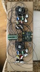
I fitted the IL Convex PSL-CV Translucent Green Arcade Button to the center of the kick panel as a power button, but I needed to fabricate something to make this work properly. So I glued a small screw to the back of the button so that when I pressed it, the screw would hit the power switch. I fitted the small power button circuit board to a piece of upright wood, held in place by a metal bracket, behind the green button.

Fabricating the power button mechanism
Once the front panel and power button were done I set to fitting the PCB feet that will support the motherboard tray ensuring I left enough room for display and USB cables to hang out the back of the board without getting blocked by the rear panel of the cabinet.

Fitting the motherboard tray
I then screwed on the motherboard and left the massive XPS power supply lying loose next to it. At a later date if I use a regular PSU I will fix it to the PC shelf. I plugged in all the components, cables, USB strip light and fans (the motherboard would not boot without the fans connected). I started preparing a wooden mount for the HDD but then stopped when I realised I wouldn’t have easy access to screw/unscrew the drive once in. I will leave it loose for now.

Arcade machine PC internals
Next I cut the FDD molex connector off so I could use it to power the amplifier. Just connect the black (ground) wire from the amp to the black ground wire from the PC molex cable, and connect the striped 12V wire from the amp to the yellow 12V wire on the molex cable, then wrap both connections in electrical tape. I mounted the amplifier to the rear of the monitor panel along with the Wi-Fi aerial.


After several test boots everything was working fine and I had a quick game of Metal Slug using an Xbox 360 Wireless Controller plugged into the front panel. OK, maybe it wasn’t a “quick” game 🙂
Step 6: Apply the graphics and kick plate
Starting with the side panel graphics, at the top I wanted my Atari logos. They are black-on-black so they are not designed to stand out but to give a subtle, smooth, raised embossed look. I gave the cabinet a wipe (very important) and followed the instructions to apply the vinyl stickers.
I then cut my Pac-Man decal into 3 pieces to fit the left side panel and applied the Retro Gamer decal to the front. I used my Spin Collective Space Invaders decal for the right side and stuck the leftover invaders on the back panel because why not. The Retro Gamer decal and Spin Collective Space Invaders decals had a lot of detail so did not stick very well to the MDF in some places. I used a clear superglue with a brush to solve that problem. In hindsight I think it may better to use the decals as stencils instead of permanent decals.


Using Adobe Illustrator CC I then set about designing my custom graphics for the marquee and control panel. Up top for the marquee I’ve used two fists punching each other – fire vs ice – which I know will look amazing when lit from behind. For the control panel I’ve used a Scorpion vs. Sub Zero image so both images will work together nicely in tandem. Once designed I had these printed onto the 3mm acrylic at a local sign shop.


The aluminium kick plate fixed on very easily indeed with just 8 screws drilled straight into the MDF kick panel.

Kick plate
Step 7: Fit the acrylic
My acrylic finally arrived. This is what I ordered…
- Screen: 2.0mm thick, 660mm x 460mm
- Marquee: 3.0mm thick, 660mm x 132mm (Qty = 2)
- Control Panel: 3.0mm thick, 660mm x 245mm
All 4 pieces of acrylic came with a 3mm hole drilled in each corner for fixing (9mm in from the edge to fit centrally to the 18mm MDF). Due to sanding I’m guessing my wood was not as wide as I thought so I had to trim my acrylic ever so slightly with the table saw which caused a few small chips. So I would recommend triple-checking the measurements of your screen area, marquee width and control panel width to ensure a smooth fitting or alternatively drop a millimetre or two off the width of the acrylic.
Starting with the screen, loosely fit the acrylic inside the cabinet and using a marker mark out the 4 corners of the monitor. Take the acrylic out, lay it flat on a table and peel back the plastic coating from the edges to go a little past the marked out corners (you want to hide as much of the monitor frame as possible so don’t be afraid to paint past the marked corners). Using masking tape create a neat rectangle for which you can spray paint the bezel. Using a glossy black spray paint, paint a coat around the edges and leave to dry. Repeat a few times until you are happy with the result.

Spray painting the acrylic screen
Next, clamp your control panel acrylic to the control panel itself. To avoid cracking ensure a tight clamp, place a piece of wood underneath and use a good quality holesaw (I used this one: Monument 1899 Vari Pitch Holesaw Kit). Using the control panel as a guide/stencil, drill the holes through the acrylic.

Cutting the control panel holes in the acrylic
Each time you cut a hole you will need to remove the acrylic from the drill bit which gets annoying, but be careful not to rush removing the bit from the drill or this happens!:

Be careful with the holesaw!
Step 8: Wire and program the control panel


As I mentioned earlier I opted for a control panel layout similar to that of the X-Arcade Joystick. So I set about threading the buttons into my control panel. I used green, red, blue, and yellow buttons as A, B, X, Y to match an XBox controller layout for when you are playing games that require you to press ‘X’ (blue) for example. The black and white buttons are the L and R bumpers and triggers. I also added black buttons to the side of the arcade machine to program for playing pinball games, and P1 and P2 buttons are on the front panel of the machine.
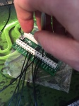
Wiring the control panel is not as confusing as it looks! As you can see I have mounted the I-PAC2 to the underside of the control panel. In order to avoid duplication or publishing out-of-date instructions, the best place to find out how to map your buttons to the I-PAC2 is here.
You programme the I-PAC2 using an application called WinIPAC V2 and instructions on how to programme it can be found here. Make sure you have upgraded your I-PAC2 to the latest firmware.
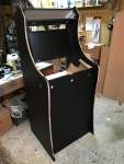
Step 9: Boot up and play!

My custom arcade machine


You can see the list of games I have here. Not all games listed are for the arcade machine and many don’t yet run on this spec PC. Those running fine on the current arcade machine are PAC-MAN, Thunder Wolves, The Walking Dead, and the Metal Slug series. The King of Fighters XIII meets the minimum requirements but does not run smoothly enough on a single core CPU. Once I upgrade to my Intel i5-2500K it will open up my arcade library significantly.
Boot and play video coming soon.
